Introduction
Short circuit protection is a critical aspect of electrical safety, preventing catastrophic failures caused by unintended current surges. A short circuit occurs when current flows through an unintended low-impedance path, potentially leading to overheating, fire hazards, and equipment failure. Effective short circuit protection strategies involve using protective devices such as fuses, circuit breakers, and relays, along with proper system coordination and grounding techniques.
This paper explores the principles of short circuit protection, device selection, maintenance, and modern advancements in protective technology.
Understanding Short Circuits
A short circuit is a fault condition where an unintended low-resistance path allows excessive current to flow. This often results in dangerous overheating and potential damage to electrical equipment.
Types of Short Circuits
Short circuits can occur in both Alternating Current (AC) and Direct Current (DC) systems, classified as follows:
- AC Short Circuits
- Phase-to-Ground Contact: A single-phase conductor makes unintended contact with the ground.
- Phase-to-Neutral Contact: A live phase touches the neutral conductor.
- Phase-to-Phase Contact: Two phase conductors come into contact.
- Inter-winding Short Circuit: A fault between windings of a transformer or motor.
- DC Short Circuits
- Pole-to-Ground Contact: A DC pole conductor contacts the ground.
- Pole-to-Pole Contact: Direct connection between two poles, causing an immediate surge in current.
Common Causes of Short Circuits
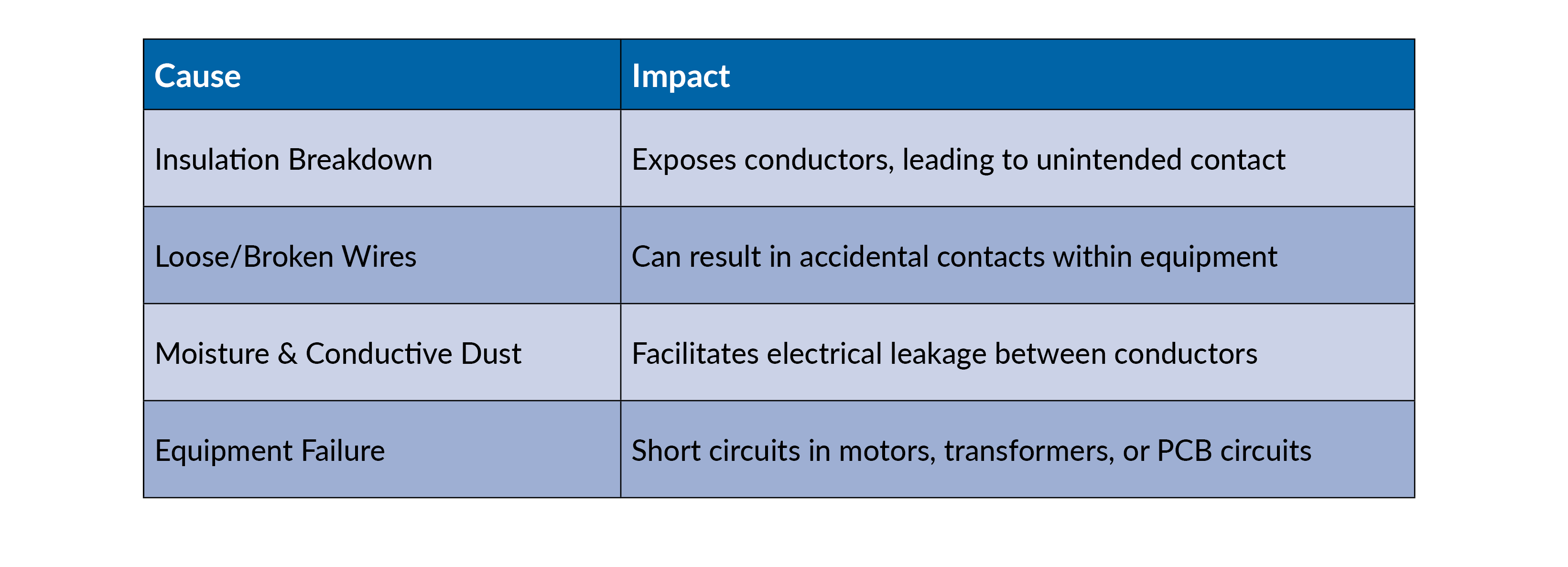
Insulation Breakdown
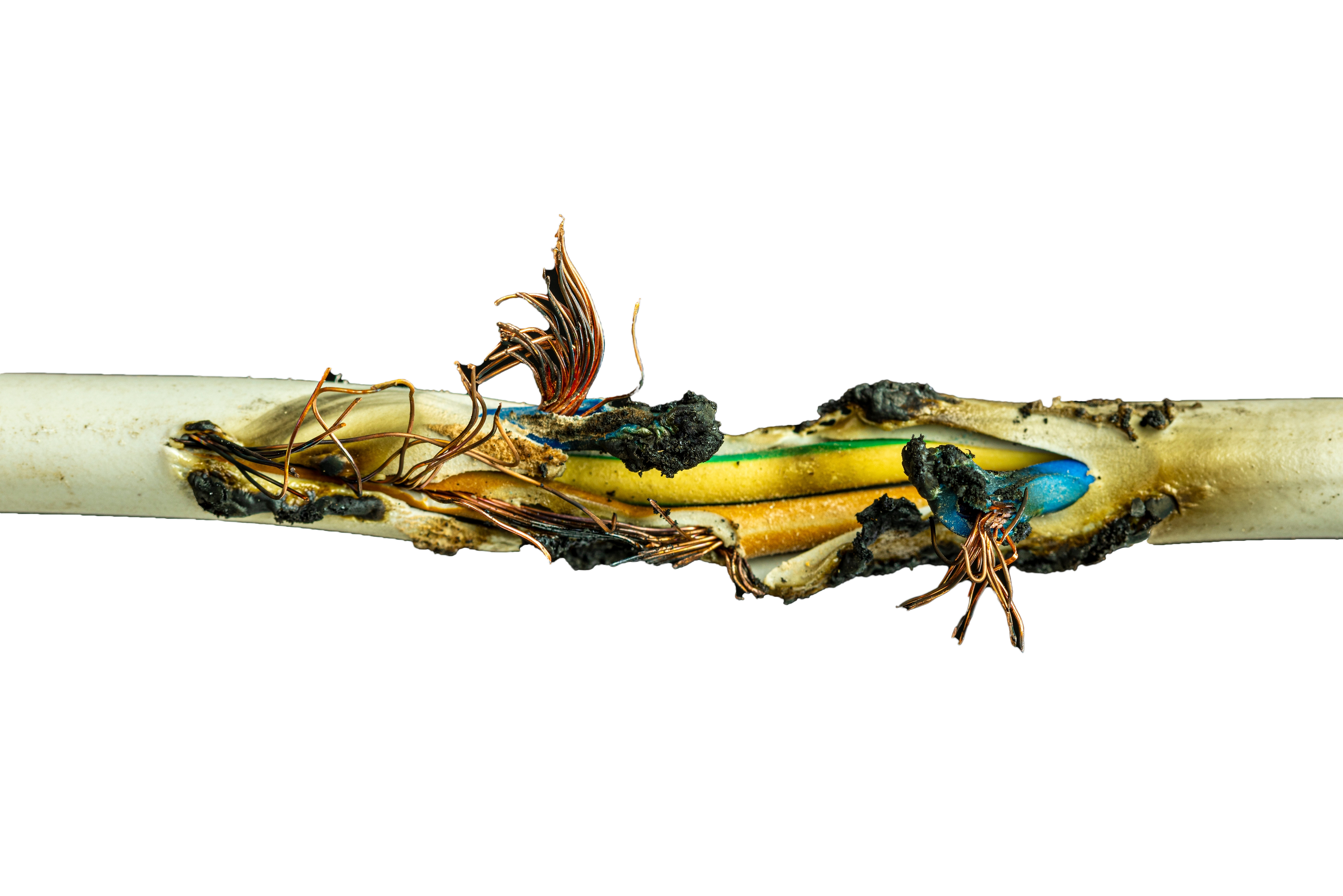
Effects of Short Circuits
A sudden surge of current—sometimes exceeding 100 times the normal operating current—can lead to:
- Thermal Phenomenon
- Melting of conductor contacts
- Damage to insulation layers
- Electrical arcing
- Destruction of bimetallic relay elements
- Electro-dynamic Phenomenon
- Mechanical stress on conductors
- Conductor repulsion inside contactors
- Distortion of motor/transformer windings
These effects highlight the necessity for proper short circuit protection devices.
Short Circuit Protection Devices
Protective devices prevent hazards by interrupting excessive current flow before it reaches destructive levels.
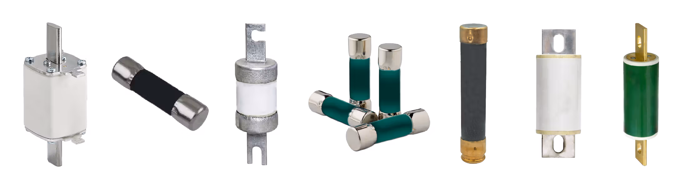
Fuses
Fuses provide single-use protection by melting a thin wire inside the fuse when excessive current flows through it.
Types of Fuses
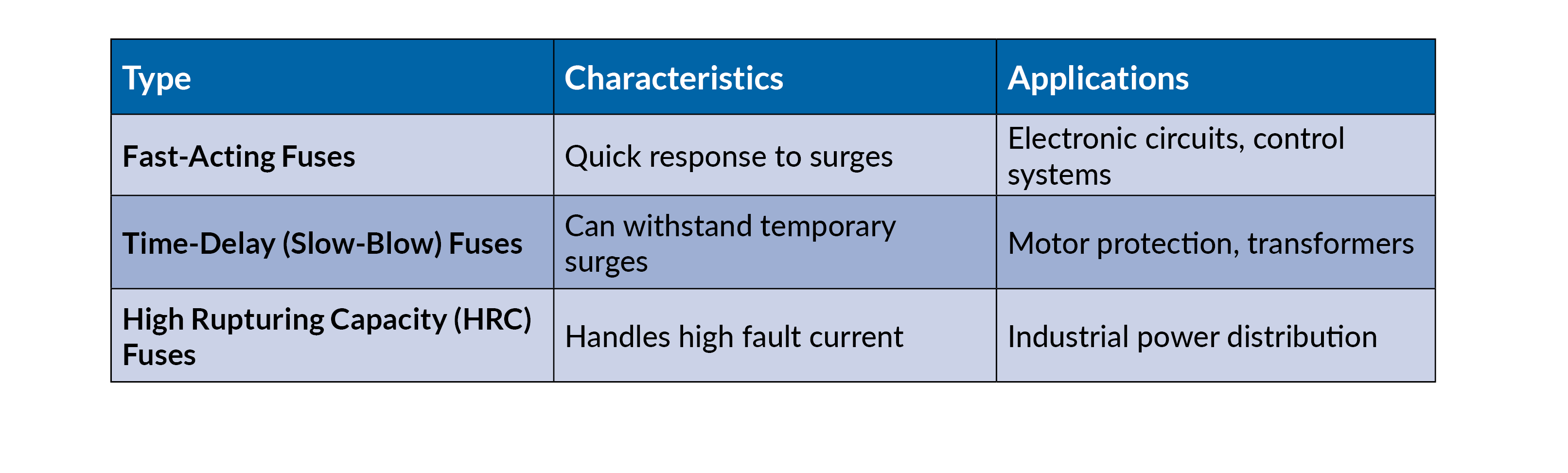
Advantages & Disadvantages
- Pros: Simple, cost-effective, reliable.
- Cons: Must be replaced after tripping.
Circuit Breakers
Circuit breakers automatically interrupt current flow when a fault is detected. Unlike fuses, they can be reset manually or automatically.
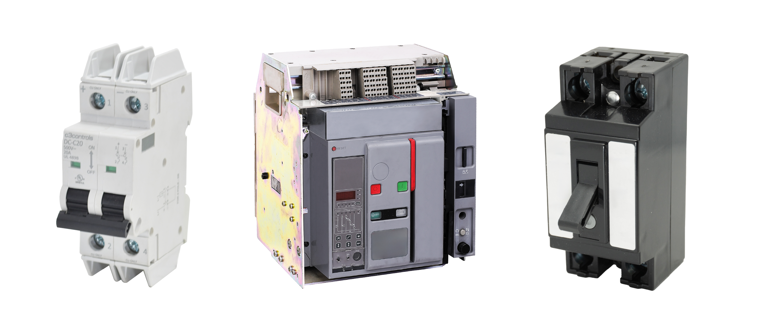
Types of Circuit Breakers
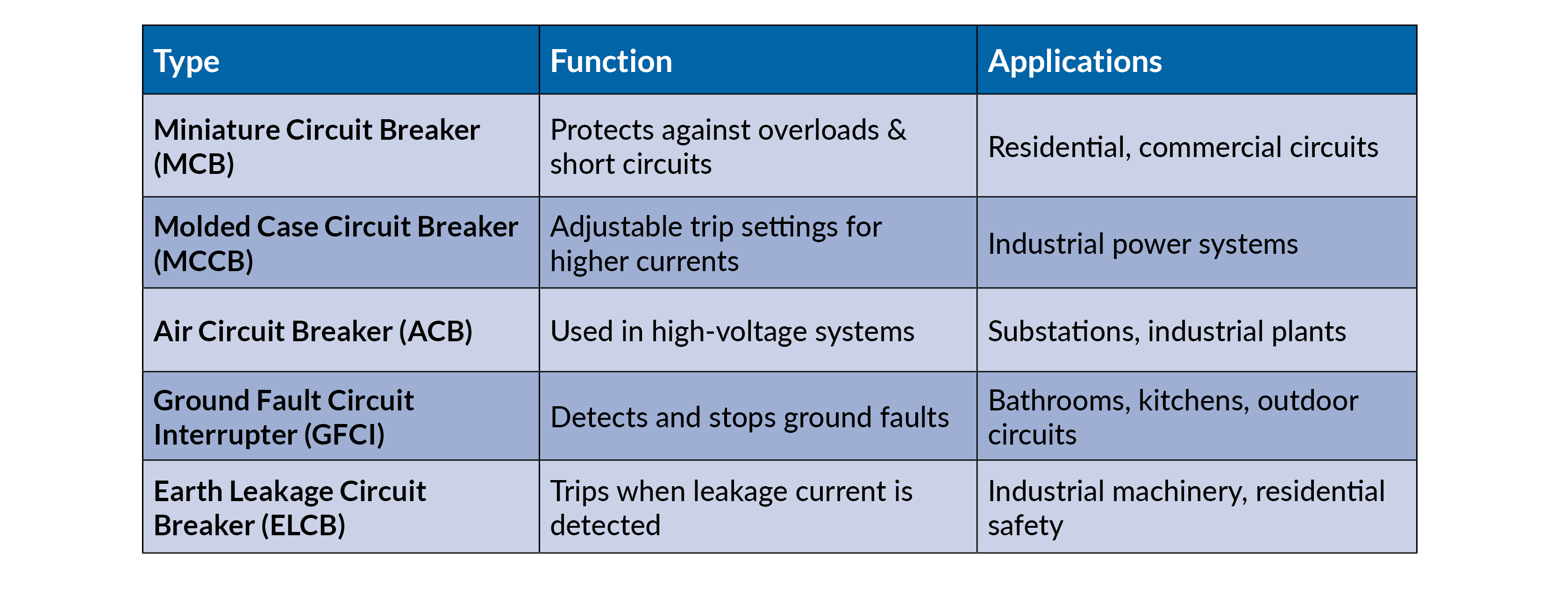
Advantages & Disadvantages
- Pros: Resettable, faster than fuses, adjustable trip settings.
- Cons: Expensive, requires periodic maintenance.
Ground Fault Protection Devices
Ground faults occur when a live conductor unintentionally connects to the ground. Protective devices detect these faults and trip the circuit.
Earth Fault Relay (EFR)
- Detects stray voltages and interrupts the circuit.
- Used in installations with high earth impedance.
Residual Current Circuit Breaker (RCCB)
- Senses leakage current and disconnects power.
- Difference from ELCB: RCCB is current-sensing, whereas ELCB is voltage-sensing.
Ground Fault Circuit Interrupter (GFCI)
- Ultra-fast response (within 1/40th of a second).
- Trips when leakage exceeds 5 mA, preventing electric shock.
- Does not protect against direct line contact hazards.
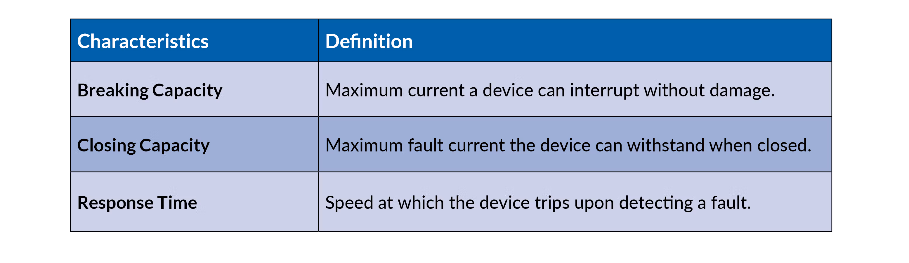
Characteristics of Short Circuit Protection Devices
Protection Coordination Strategies
Proper coordination ensures the most appropriate device trips first, minimizing disruptions.
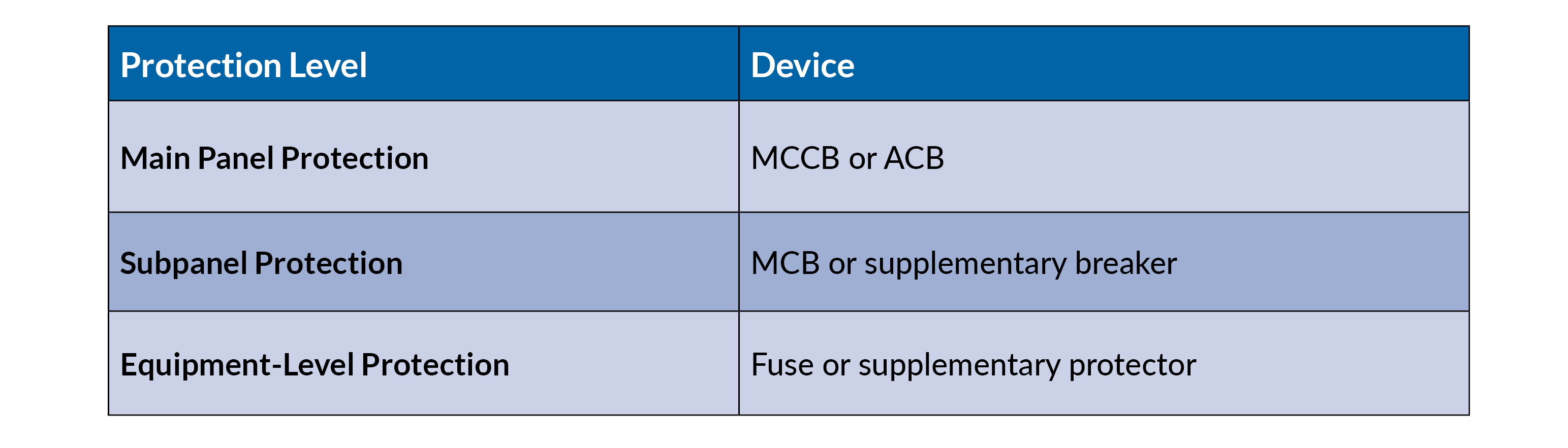
Selective Tripping: The closest protection device to the fault trips first, preventing upstream breakers from shutting down an entire system.
Greetings Earthing

Earthing & Grounding for Short Circuit Protection
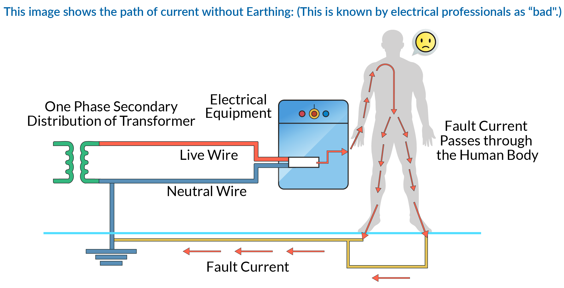
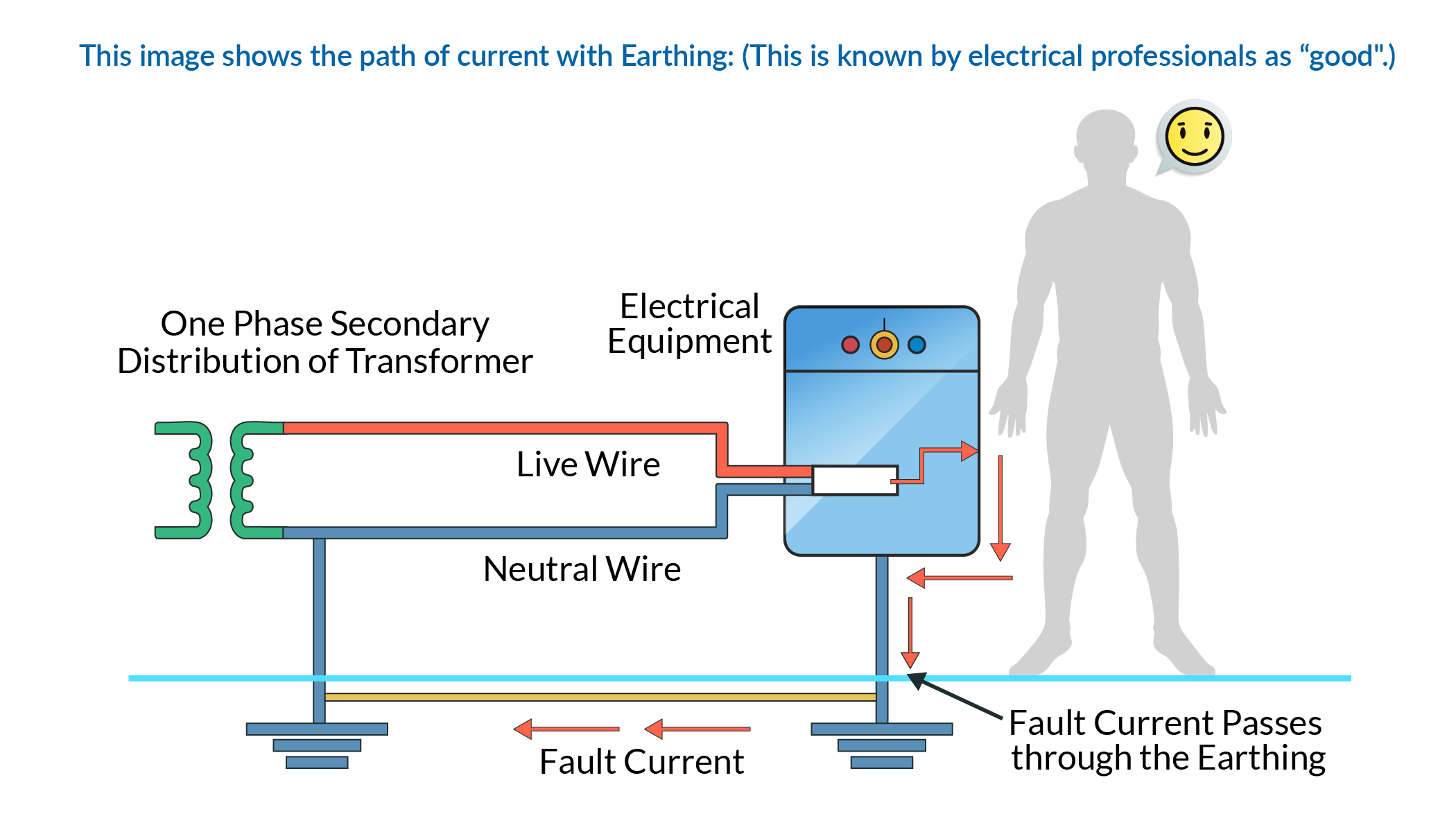
Electrical Earthing diverts excess current safely to the ground, preventing equipment damage and shock hazards. “Earthing” literally means the metal frame of the electrical device is connected to the Earth.
Earthing is critical for the following reasons:
- Protect users from electrical shock.
- Earthing provides the easiest and safest path for a fault current. Moreover, it maintains the path even if the insulation fails.
- It protects expanse and sometimes fragile electrical and electronic equipment from high voltage surges, short circuit events and lighting strokes.
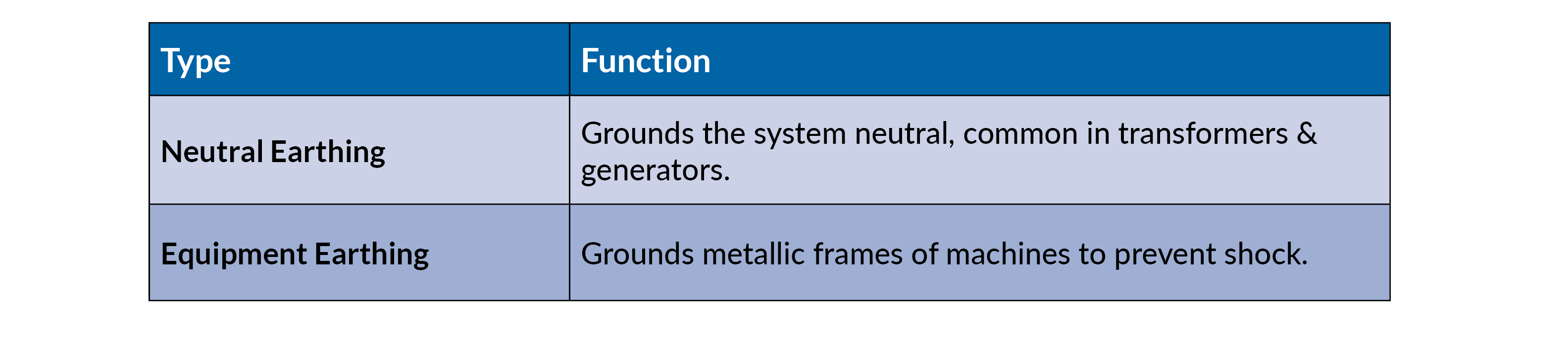
Types of Earthing
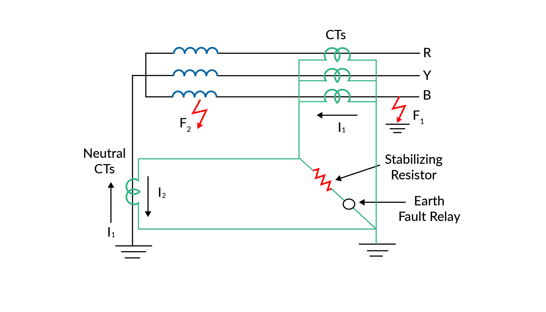
Restricted Earth Fault Protection (REFP)
- Uses a current differential scheme to detect internal earth faults.
- Only operates for faults inside the protective zone, reducing unnecessary trips.
Ground Resistance Measurement
The Fall of Potential Method is used to measure electrode resistance using an Earth Tester.
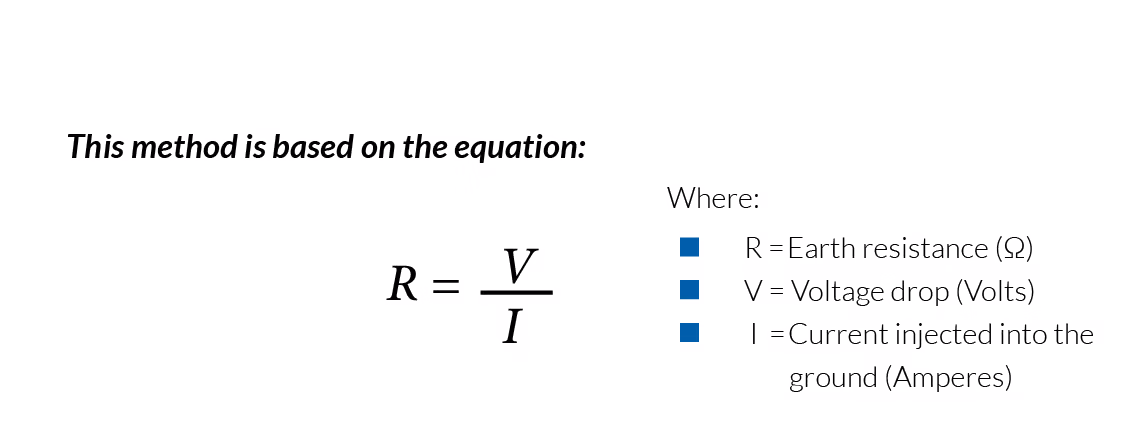
The Fall of Potential Method is a widely used technique to measure the earth electrode resistance (also called ground resistance). It works by applying a known current into the earth and measuring the resulting voltage drop to calculate resistance using Ohm’s Law.
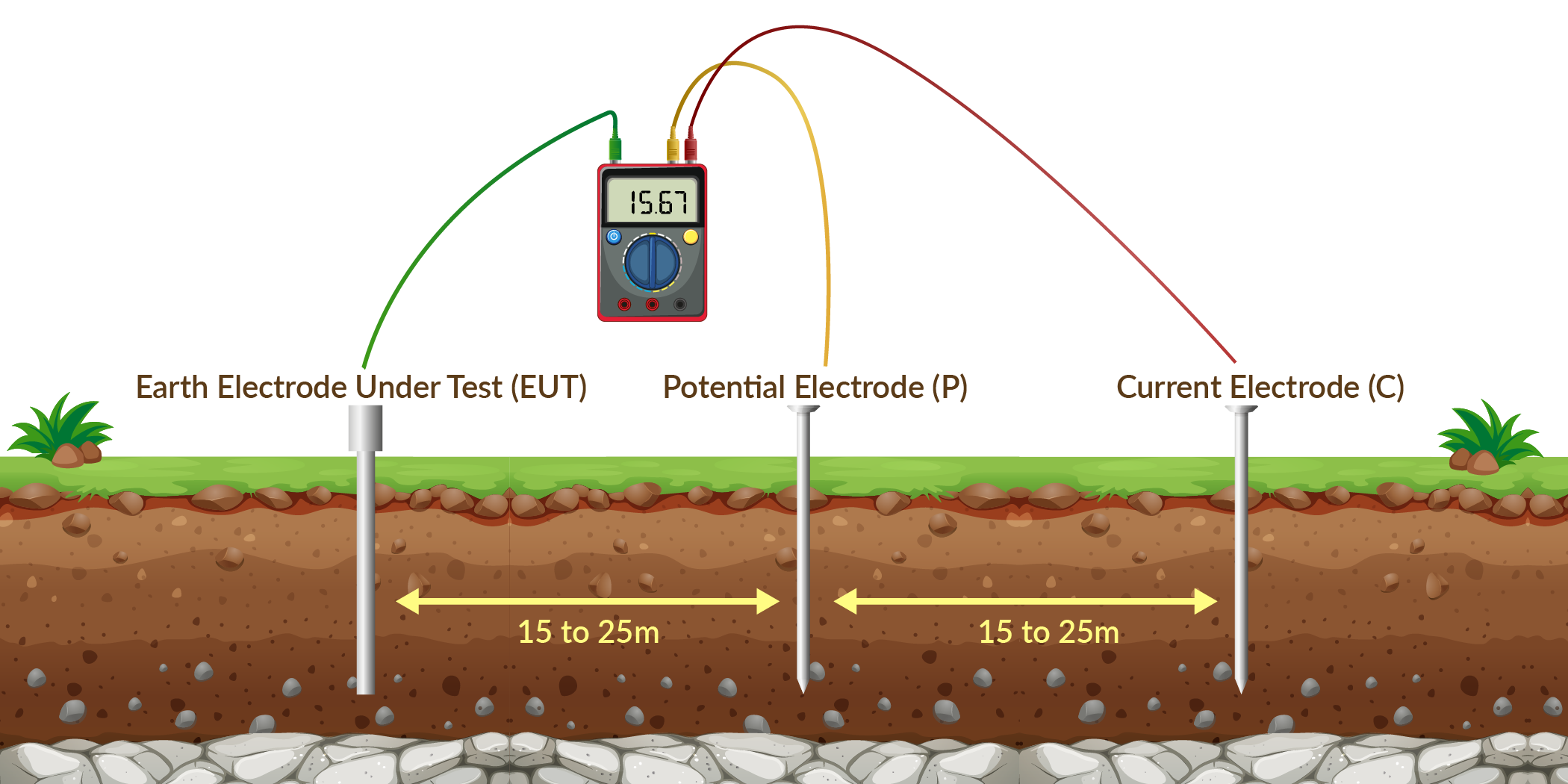
Test Setup & Procedure
To perform the test, three electrodes are used:
- Earth Electrode Under Test (EUT): The electrode whose resistance is being measured.
- Current Electrode (C): A test electrode placed some distance away to inject current into the earth.
- Potential Electrode (P): A probe placed between the EUT and the current electrode to measure voltage.
Step-by-Step Process
- Inject Current: A known AC or DC test current is injected between the Earth Electrode (EUT) and Current Electrode (C).
- Measure Voltage: The voltage difference is measured between the Earth Electrode (EUT) and Potential Electrode (P).
- Calculate Resistance: Using Ohm’s Law, R=V/IR = V/IR=V/I, the ground resistance is determined.
Fall of Potential Method in Practice
Advantages of the Fall of Potential Method
- Accurate Measurement: Provides precise earth resistance values.
- Simple & Reliable: Easy to perform with basic instruments.
- Applicable to Various Installations: Works for transformer substations, communication towers, etc.
Limitations
- Electrode Spacing Matters: Incorrect distances between electrodes can lead to inaccurate readings.
- Interference from Nearby Conductors: Underground utilities may affect results.
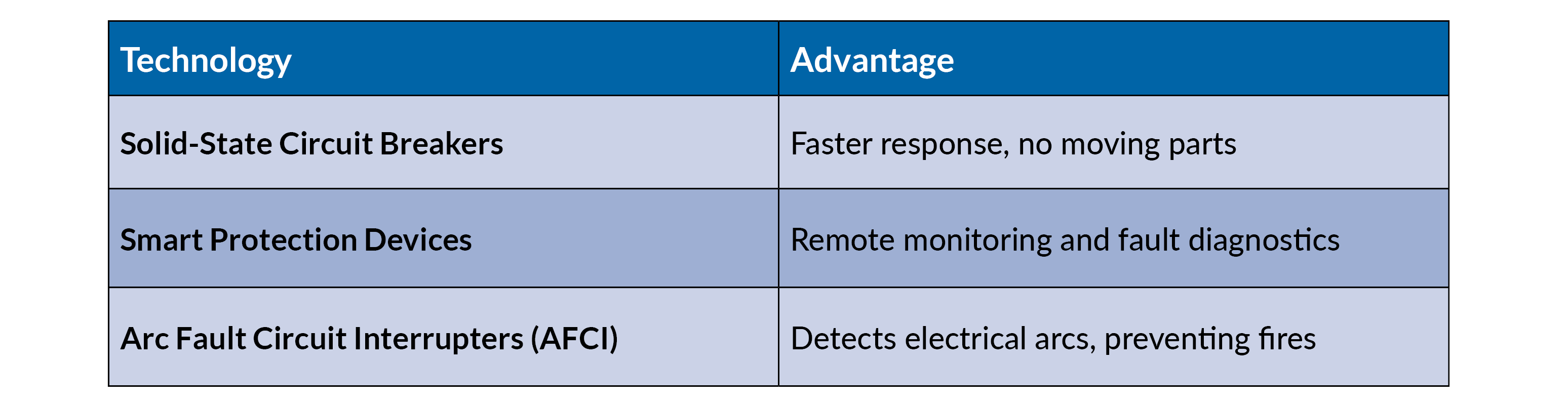
Modern Advancements in Short Circuit Protection
Conclusion
Short circuit protection is essential for maintaining electrical system safety and reliability. By selecting appropriate fuses, circuit breakers, and ground fault protection devices, engineers can mitigate risks, minimize downtime, and comply with safety regulations.
Key Takeaways:
- Proper coordination ensures selective tripping and system integrity.
- Regular maintenance and testing prevent unexpected failures.
- Advancements in smart protection enhance fault detection and system diagnostics.
A well-designed short circuit protection system safeguards lives, equipment, and infrastructure, making it a fundamental aspect of electrical engineering design.
----------------------------------------
Disclaimer:
The content provided is intended solely for general information purposes and is provided with the understanding that the authors and publishers are not herein engaged in rendering engineering or other professional advice or services. The practice of engineering is driven by site-specific circumstances unique to each project. Consequently, any use of this information should be done only in consultation with a qualified and licensed professional who can take into account all relevant factors and desired outcomes. The information was posted with reasonable care and attention. However, it is possible that some information is incomplete, incorrect, or inapplicable to particular circumstances or conditions. We do not accept liability for direct or indirect losses resulting from using, relying or acting upon information in this article.
ISO 9001:2015
Certified
17+ Million Product
Configurations
Lifetime
Warranty
Guaranteed
Same-Day Shipping
Advantage Pricing
Save Up To 40%
c3controls Headquarters, USA
664 State Avenue
Beaver, PA 15009