Check out our line of open & enclosed motor starter assemblies designed to provide reliable and accurate protection against overload and phase loss conditions.
Single catalog number simplifies the bill of material and ordering process!
Introduction to Motor Starters
Motor starters are one of the major inventions for motor control applications. As the name suggests, a starter is an electrical device which controls the electrical power for starting a motor. These electrical devices are also used for the purpose of stopping, reversing and protecting electric motors. The following are the two major components of a starter:
- Contactor: The main function of the contactor is to control the electric current to the motor. A contactor can make or break power to the circuit.
- Overload Relay: Overheating and drawing too much current can cause the motor to burn out and become practically useless. Overload relays prevent this from happening and protect the motor from any potential danger.
A starter is an assembly of these two components, which allows it to turn on or off an electric motor or motor controlled electrical equipment. The starter also provides the necessary overload protection to the circuit.
Types of Motor Starters
There are several types of motor starters. However, the two most basic types of these electrical devices are:
Manual Starters
Manual starters are devices that are operated manually. These starters are extremely easy and straightforward to operate and do not require expert intervention. The starter includes a button (or rotary knob) which enables a user to turn the connected equipment on or off. The buttons feature mechanical linkages, which make the contacts open or close, starting or stopping the motor. However, it's important to note that this type of starter does not break a control circuit during a power loss, which means the motor could restart automatically when the incoming voltage is restored. This could be a critical safety consideration in some applications.
The following features of a manual starter make it a preferred choice over other types:
- These starters deliver a safe, as well as economical operation.
- The compact size of these devices make them suitable for a wide range of applications.
- They provide overload protection to the motor, protecting it from any potential damage.
- These devices come with a vast choice of enclosures.
- The initial cost of the manual starter is low.
By understanding both the operation and the features of manual starters, users can make informed decisions about their suitability for specific applications, balancing considerations of safety, cost, and functionality. The mechanical simplicity of manual starters, coupled with their robust safety features, makes them a reliable choice for many industrial needs.
Magnetic Motor Starters
This is the other main type of motor starter. It is operated electromagnetically. It means that the motor load connected to the motor starter is typically started and stopped using a lower and safer voltage than the motor voltage. The magnetic motor starter relies on energizing a coil to close and hold the contacts. During a power failure, it automatically breaks the control circuit, and the holding contacts open, thus removing power to the motor.
Just like other motor starters, the magnetic starter also has an electrical contactor and overload relay to protect the device from too much current or overheating. Additionally, magnetic motor starters include protection against low voltage and overcurrent, enhancing their reliability and safety in various industrial applications.
Furthermore, a type commonly referred to as Direct Online (DOL) operates the coil with the main incoming voltage. There is no voltage reduction involved, which simplifies the design but is generally suitable for motors 5 HP and below. This type of starter features two simple push buttons for starting and stopping the motor, making it user-friendly. The overload relay in these starters plays a crucial role in providing protection from overheating and overcurrent, ensuring the motor operates within safe conditions.
Incorporating both disconnects and short-circuit protection, often in the form of fuses or circuit breakers, combination motor starters are an enclosed unit that provides a comprehensive solution by integrating the essential components of a motor starter into one compact assembly. This configuration not only saves space but also simplifies installation and maintenance, making it a preferred choice for many industrial setups.
Motor Starter Circuitry & Operation
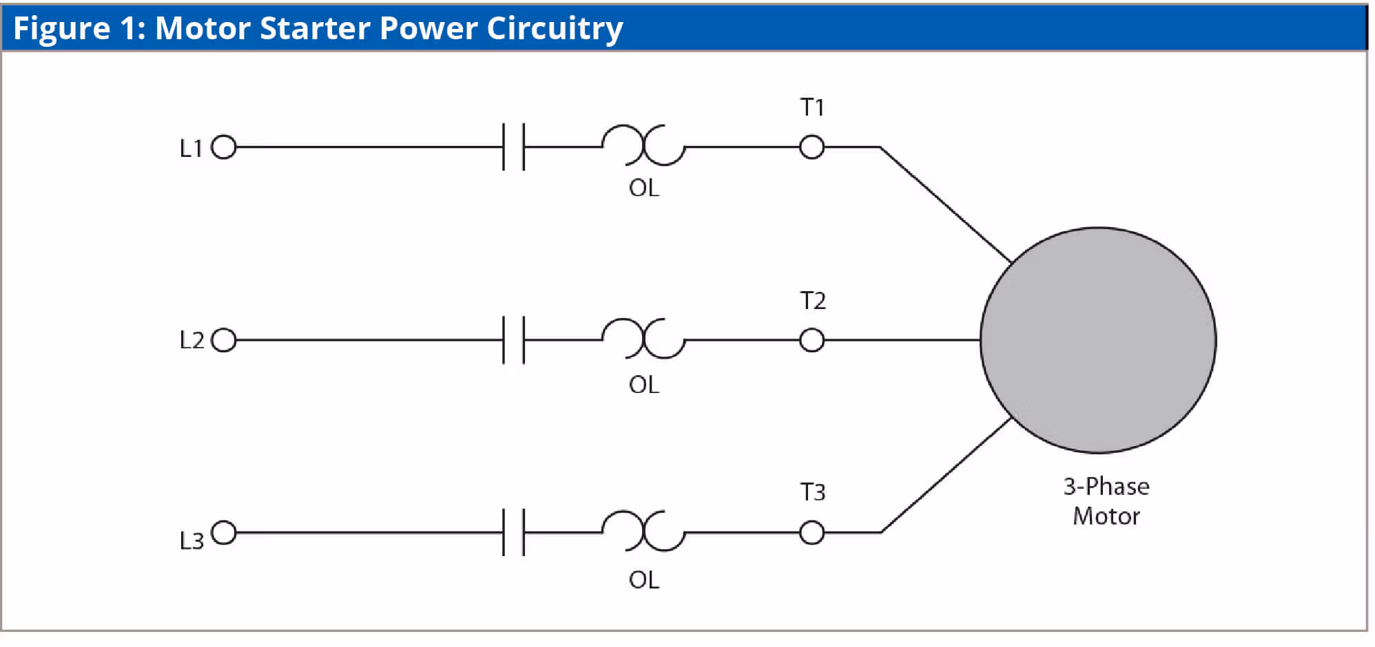
There are two circuits in a motor starter, which are as follows:
- Power Circuit: The power circuit connects the line to the motor. It provides transmission of electricity through the starter contacts, overload relay, and then to the motor. The motor current is carried by the power (main) contacts of the contactor.
- Control Circuit: This is the other motor starter circuit, which operates the contactor to turn it on or off. The contactor main contacts are responsible for allowing or interrupting the flow of current to the motor. To do this, the contacts in the control circuit are either opened or closed. The control circuit energizes the contactor coil, which creates an electromagnetic field. The power contacts are pulled by this electromagnetic field to a closed position. This completes the circuit between the motor and the line. This way, remote operations are made possible by the control circuit. The control circuit can be wired in the following two ways:
- Method 1: One of the most widely used methods employed for wiring the control circuit is referred to as the “Two-wire method”. A maintained contact type of pilot device like presence sensor, thermostat, or float switch is used in the two-wire method of wiring the control circuit.
- Method 2: Unlike the two-wire method, the “Three-wire method” of wiring the control circuit uses a holding circuit contact and the momentary contact pilot devices.
The control circuit can derive the power from either of the following three ways:
- Common Control: This type of control is when the power source of the control circuit is the same as the motor.
- Separate Control: This is the most popular type of control. As the name suggests, the control circuit derives power from a separate source in this arrangement. Generally, the power derived is lower in voltage as compared to the motor’s power source.
- Transformer Control: As the name suggests, the control circuit derives power from a control circuit transformer. Generally, the power derived is lower in voltage as compared to the motor’s power source.
Types of Magnetic Motor Starters
Depending on how they are connected in a circuit, there are many types of magnetic motor starters, such as:
1. Direct-On-Line Starter
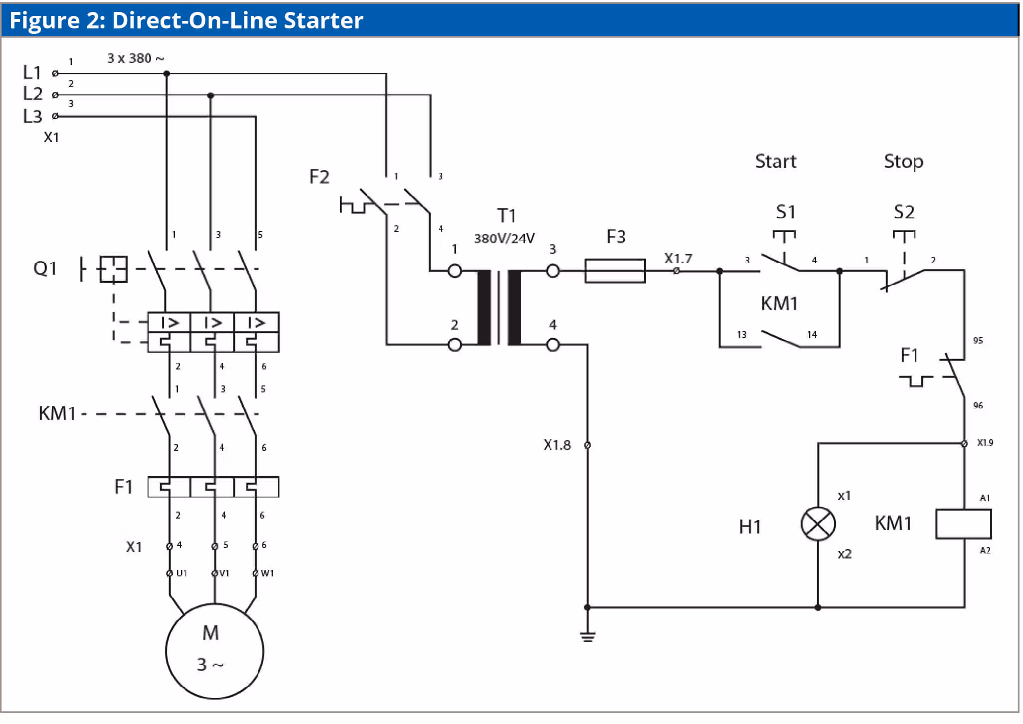
The direct-on-line starter is the simplest form of motor starter, other than a manual starter. The controller of this starter is typically a simple push button (but could be a selector switch, limit switch, float switch, etc.). Pressing the start button closes the contactor (by energizing the contactor coil) connected to the main supply and motor. This provides the supply current to the motor. To turn the motor off, a stop button is provided. To protect it from over current, the control circuit is wired through a normally closed auxiliary contact of the overload relay. When the overload relay trips, the normally closed auxiliary contact opens, and de-energizes the contactor coil, and the contactor main contacts open.
The Advantages of Using Direct-On-Line Motor Starters:
- They have a compact design.
- They are cost-effective.
- They have a simple construction.
2. Rotor Resistance Starter
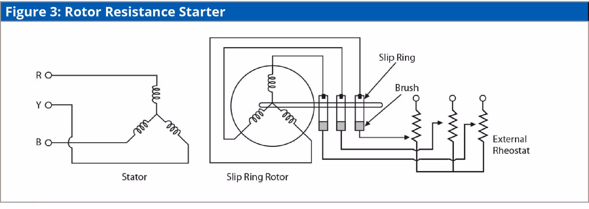
In the rotor resistance starter, the three resistances are connected such that they are in series with the rotor windings. This helps reduce the rotor current considerably, as well as increases the motor torque.
The Advantages of Using Rotor Resistance Motor Starters:
- They are cost-effective.
- They have a simple speed control method.
- They provide low starting current, large starting torque, and large pull-out torque.
3. Stator Resistance Starter
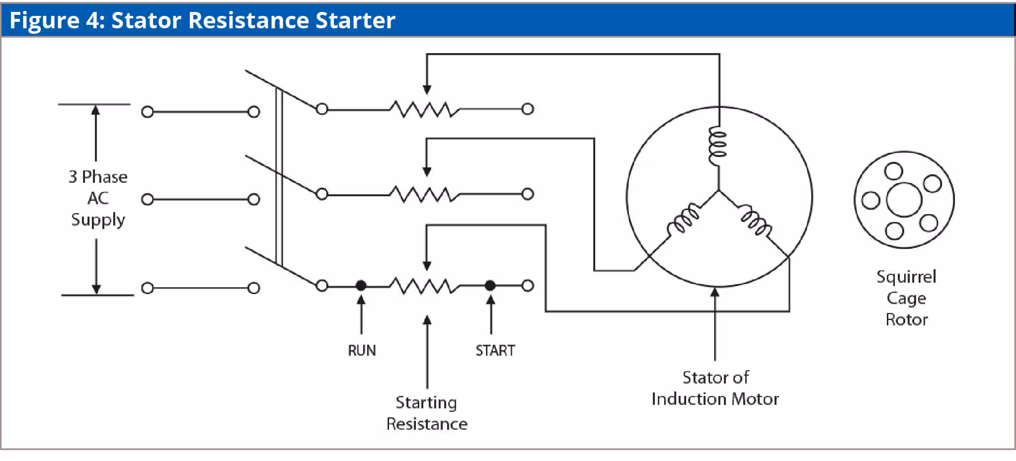
The stator resistance starter consists of three resistors, which are connected in series with each phase of the stator windings. At each resistor, a voltage drop is caused, so it becomes necessary to apply low voltage to each phase. These resistances are set at the start or maximum position during the motor start stage. The starting current is kept at a minimum in this type of starter. Also, the starting torque to the motor needs to be maintained.
The Advantages of Using Stator Resistance Motor Starters:
- They are suitable for use in speed control applications.
- They have extremely flexible starting characteristics.
- They provide smooth acceleration.
4. Auto Transformer Starter
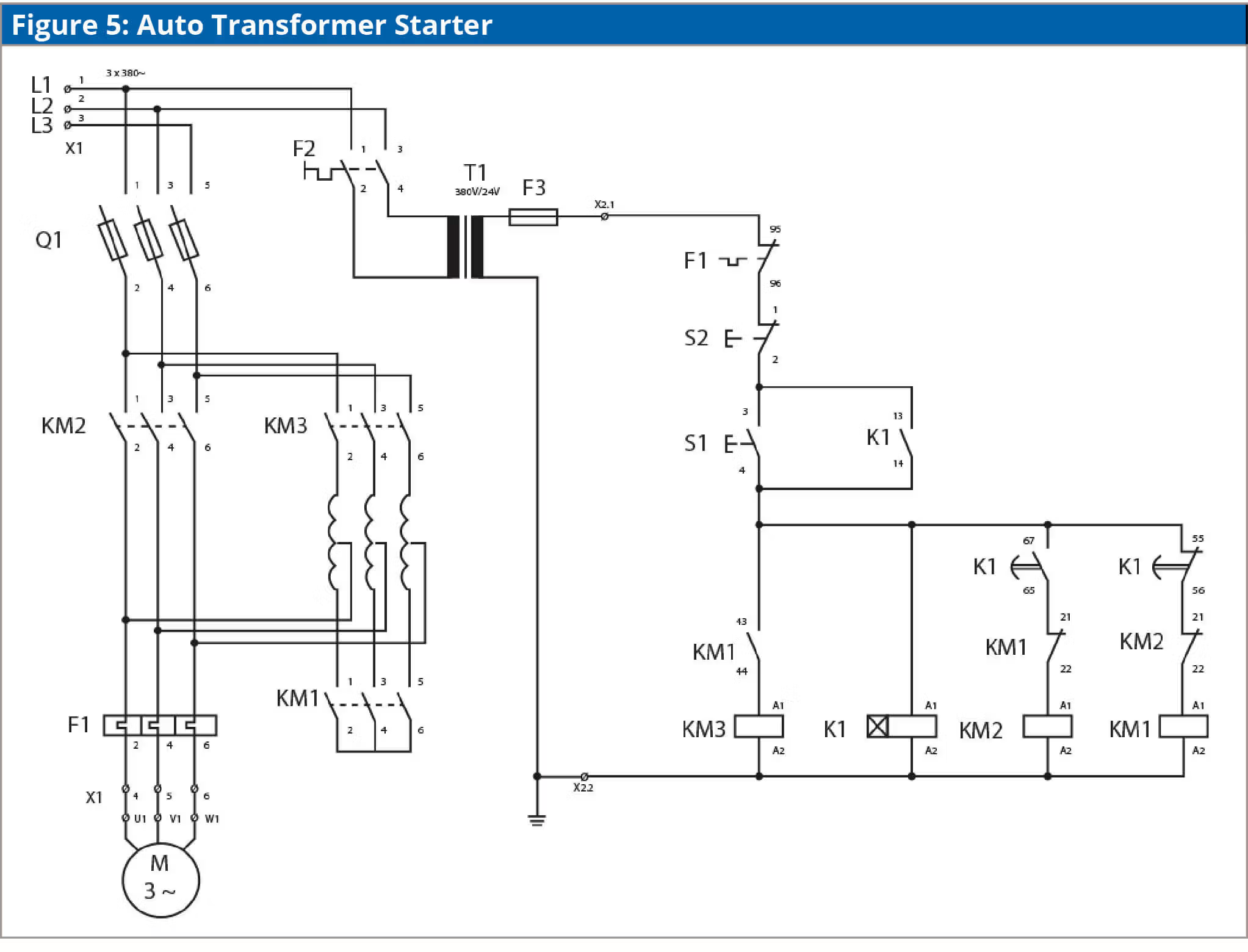
With an auto transformer starter, the transformer supplies a certain percentage of the primary voltage to the secondary of the transformer. The auto transformer is connected in a star configuration. The three tapped secondary coils of the transformer are connected to the three motor phases in this type of starter. This helps in reducing the voltage that is being applied to the motor terminals.
The Advantages of Using Auto Transformer Motor Starters:
- They can be used for manual speed control, but with limited options.
- They have extremely flexible starting characteristics.
- They have a high output torque.
5. Star Delta Starter
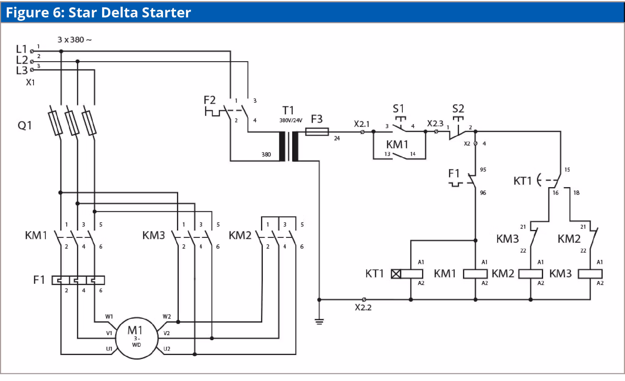
Compared to the other types of starters, the star delta starter is used on a large scale. As the name suggests, the three windings are connected in a star connection in the star delta starters. A certain time is set by the timer or any other controller circuit. After this time is passed, the windings are then connected in the delta connection. The phase voltage in the star connection is reduced to 58%, and the total current drawn is 58% of normal current. This results in a reduced torque.
The Advantages of Using Star Delta Motor Starters:
- They are ideal for long acceleration times.
- They have a lower input surge current when compared to other starters.
- They have a simpler construction as compared to other starters.
6. VFD Starter
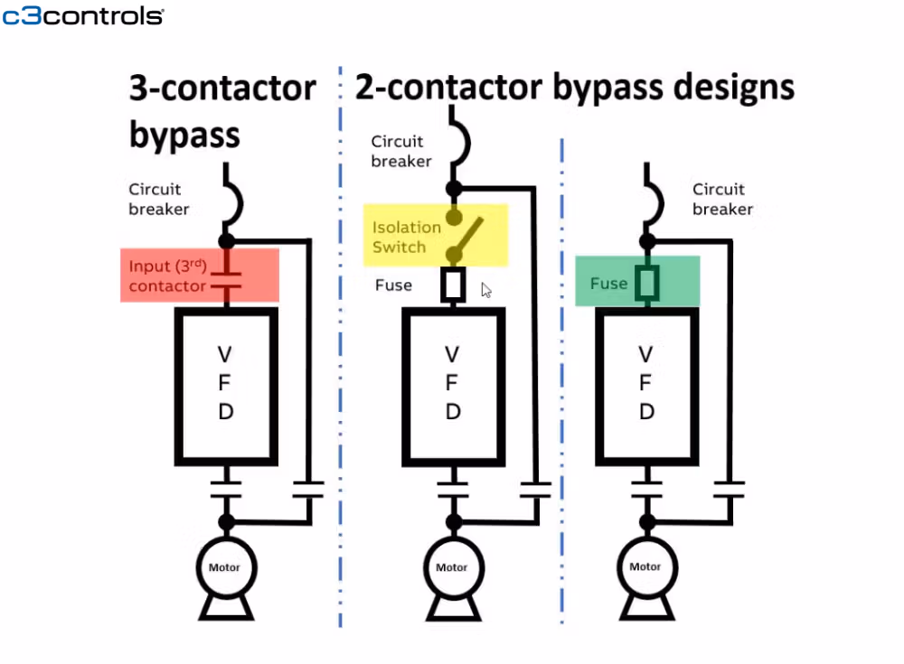
An AC drive, also known as a Variable Frequency Drive (VFD), is a crucial electronic device that regulates the speed of an AC motor by adjusting the frequency of the electrical power supply. This helps in starting, stopping, and running the motor more efficiently and smoothly. VFDs are commonly used in industrial and commercial applications to save energy, reduce mechanical stress, and improve process control. They are especially useful for applications where precise motor speed control is required, such as in conveyors and fans.
Applications of VFDs Starter
- HVAC Systems: VFDs are essential for controlling fans and pumps, optimizing airflow and water circulation.
- Industrial Conveyors: Perfect for managing the speed and torque of conveyor belts, ensuring efficient material handling.
- Food Processing: Used in mixers and grinders to maintain consistency and quality of food products.
- Mining and Construction: Perfect for stone crushers, providing precise control to handle various material types and sizes.
- Elevator and Escalator Systems: Enhance the control and safety of elevators and escalators, offering smooth operation and energy savings.
Benefits of VFDs Starter
- Energy Savings: Reduces energy consumption by aligning motor speed with demand.
- Smooth Motion: Controlled acceleration and deceleration minimize wear.
- Versatility: Applicable to various types of industrial machinery.
- Precision Control: Maintains consistent equipment speed.
- Advanced Features: Includes PLC-like programming and built-in protection.
- Real-Time Diagnostics: Provides ongoing monitoring and communication for efficient maintenance.
Features of Motor Starters
Today, motor starters are used on a large scale due to their list of beneficial features. The following are some features of these highly useful electrical devices:
- They facilitate the starting and stopping of the motor.
- The starters are rated by power (horsepower, kilowatt) and current (amperes).
- They provide the necessary overload protection for the motor.
- The electrical device facilitates remote on/off control feature.
- These devices allow you to make and break current rapidly (plugging and jogging).
Fundamental Functions of Motor Starters
The following are the most fundamental functions that a starter has to perform:
- Control: The control function is mainly carried out by the contactor component of a starter. It is controlling the opening and closing of the power electrical circuit. The switching is done by the main contacts (poles) of the contactor. An electromagnetic coil is energized, which open or close the contacts. This electromagnetic coil has a nominal control voltage, and can either be an AC or DC voltage.
- Short-Circuit Protection: In industrial applications, normal load current can be up to thousands of amperes. In the case of a short-circuit fault, the fault current can go over 100,000 amperes. This can cause severe damage to the equipment. The short-circuit protection disconnects the supply and prevents the potential damage in a safe manner. Short circuit protection is provided by fuses or circuit breakers in a Combination Motor Controller.
- Overload Protection: When a motor draws more current than it is designed to, an overload condition is caused. The main objective of an overload relay is to detect the excess currents. When an overload is detected, the auxiliary contact of the overload relay opens the circuit and prevents the motor from burning out or overheating. Electronic or electromechanical overload relays are used in combination with a contactor to provide the required overload protection.
- Disconnecting and Breaking: In order to prevent an unintended restart, it is required to disconnect the motor from the main power circuit. In order to safely perform maintenance on a motor or starter, a motor must be able to switch off and be isolated from the power. The disconnect switch of the circuit provides this function. Disconnecting and breaking is provided by a disconnect switch or circuit breaker in a Combination Motor Controller (or can be installed remotely from the starter).
Standards and Ratings
There are many factors involved in motor starter ratings, such as thermal current, continuous current, motor voltage, and power.
The thermal current is dependent on the thermal conductivity (k), which is the property indicating the heat conducting ability of a material. It means that thermal current is directly proportional to the thermal conductivity.
The continuous current, which is also commonly referred to as the continuous ampere rating is a measure of the capability of the motor control starter to handle current for a continuous time.
The power rating of the motor starter is based on the type of motor used. DC motor starters have ratings for DC horsepower. On the other hand, AC motor starters have a single-phase power and three-phase power rating.
The rating of the motor starter is based on the size and type of load for which it was designed. Starters conform to the standards and ratings from Underwriters Laboratories (UL), Canadian Standards Association (CSA), International Electrotechnical Commission (IEC) and National Electrical Manufacturers Association (NEMA).
NEMA Rating
The NEMA ratings of a starter depends largely on the maximum horsepower ratings given in the National Electrical Manufacturers Association ISCS2 standard. The selection of the NEMA starters is done on the basis of their NEMA size, which varies from Size 00 to Size 9.
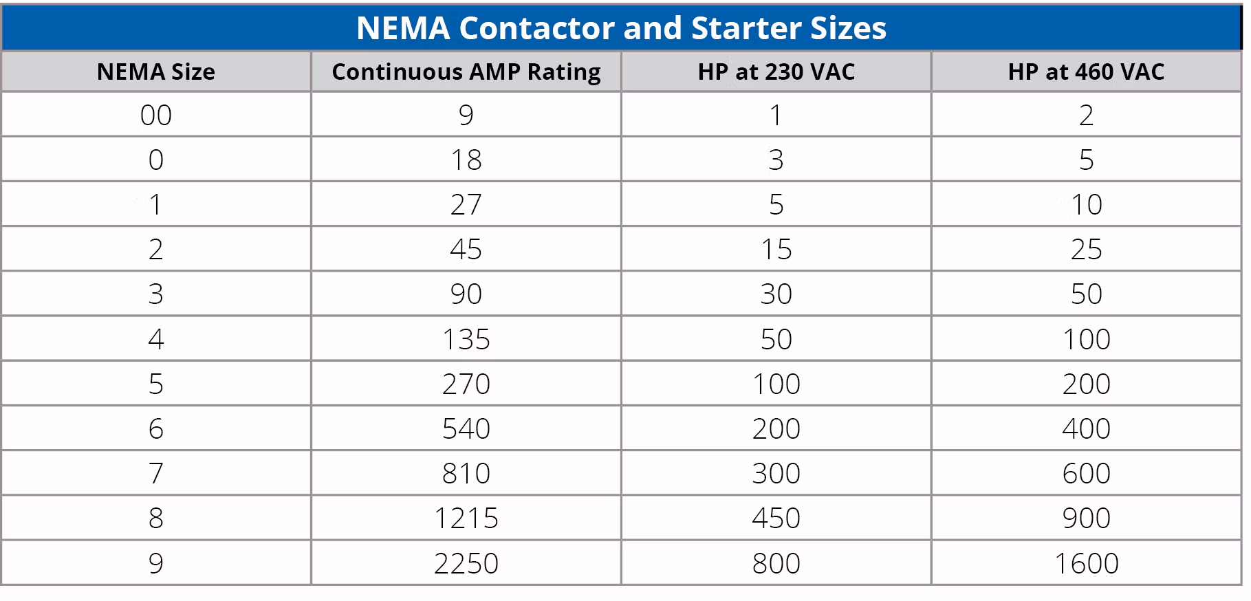
The NEMA starter, at its stated rating, can be used for a wide range of applications, ranging from simple on and off applications to plugging and jogging applications, which are more demanding. It is necessary to know the voltage and horsepower of the motor when selecting the proper NEMA motor starter. In the case where there is a considerable amount of plugging and jogging involved, then derating a NEMA-rated device will be required.
IEC Rating
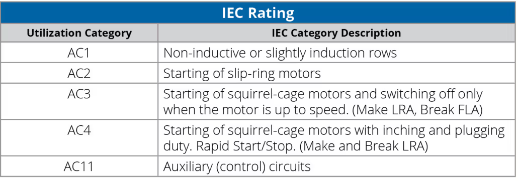
The International Electrotechnical Commission (IEC) has specified the operational and performance characteristics for IEC devices in the publication IEC 60947. Standard sizes are not specified by the IEC. The typical duty cycle of IEC devices are defined by utilization categories. As far as general motor starting applications are concerned, the AC3 and AC4 are the most common utilization categories.
Unlike NEMA sizes, they are typically rated by their maximum operating current, thermal current, HP and/or kW rating.
There are other parameters that are important to consider, while selecting motor starters, such as time-limit acceleration, current-line acceleration, control voltage, number of poles, and operating temperature. We will cover those in a future white paper.
We hope that this short white paper has given you a good, basic understanding of motor starters. Look for other papers from c3controls at c3controls.com/blog.
Disclaimer:
The content provided in this white paper is intended solely for general information purposes and is provided with the understanding that the authors and publishers are not herein engaged in rendering engineering or other professional advice or services. The practice of engineering is driven by site-specific circumstances unique to each project. Consequently, any use of this information should be done only in consultation with a qualified and licensed professional who can take into account all relevant factors and desired outcomes. The information in this white paper was posted with reasonable care and attention. However, it is possible that some information in these white papers is incomplete, incorrect, or inapplicable to particular circumstances or conditions. We do not accept liability for direct or indirect losses resulting from using, relying or acting upon information in this white paper.
ISO 9001:2015
Certified
17+ Million Product
Configurations
Lifetime
Warranty
Guaranteed
Same-Day Shipping
Advantage Pricing
Save Up To 40%
c3controls Headquarters, USA
664 State Avenue
Beaver, PA 15009