Introduction to Switchgear Systems
Switchgear systems play a critical role in power distribution networks, providing control, protection, and isolation for electrical circuits. The shift from basic fuse-based protection to advanced DC MCBs (Miniature Circuit Breakers) rated for 250V DC per pole has significantly improved the protection of control circuits in modern installations.
Core Switchgear Components
A typical switchgear assembly includes circuit breakers (SF6, vacuum, or air-insulated), protection relays, instrument transformers, and busbars. Often overlooked are the control circuit protection devices, which are essential for ensuring the reliable operation and longevity of these primary components.
Control Circuit Protection Requirements
Standard control voltages in North America typically operate at 125V DC, while European systems use 110V DC. With the trend towards higher voltage systems up to 250V DC for improved efficiency and reduced current draw, 250V DC-rated MCBs have become valuable for future-proofing installations.
Advantages of 250V DC Per Pole MCBs
Universal Application
- Compatible with all common control voltages (24V, 48V, 125V, 250V DC)
- Eliminates the need for multiple SKUs, simplifying inventory management
Enhanced Safety Margins
- Rated well above standard 125V DC systems
- Capable of handling transient voltage spikes without degradation
- Provides added safety for aging or legacy systems
Superior Arc Interruption
- Equipped with specialized arc chutes for efficient DC interruption
- Tested for multiple interruption cycles, ensuring long-lasting contact integrity
Space and Cost Efficiency
- Compact design reduces panel space requirements
- Lowers installation costs by eliminating the need for multiple components
Clear Operation Status
- Built-in indicators provide visible operational status, enhancing system monitoring
Resettable Operation
- Unlike fused solutions, MCBs are resettable, offering a cost-effective and sustainable solution for maintenance
Comparison to Traditional Protection Solutions
Limitations of Conventional Solutions
Standard AC MCBs and Traditional DC MCBs
- Standard AC MCBs are also rated for 48 to 60V DC (per pole), requiring series connections for higher voltages, which increases panel space requirements.
- Traditional DC MCBs are often limited to a 125V DC rating and may require two poles in series for higher voltage, leading to higher installation and maintenance costs.
- Series-connected poles lead to uneven voltage distribution across contacts. During switching operations, the asynchronous opening of poles creates voltage imbalance, causing the first pole to bear excessive electrical stress. Additionally, the higher contact resistance of series-connected poles results in increased power losses in the circuit.
Fused Solutions
- Designed for one-time operation, requiring replacement after each fault, and lack visible operation indicators, making system monitoring more difficult.
Application Examples
Breaker Control Circuit Protection
A critical application for DC MCBs is in circuit breaker control schemes, where they protect both the close and trip circuits. The following image shows a typical circuit breaker control schematic where a DC MCB would be utilized.
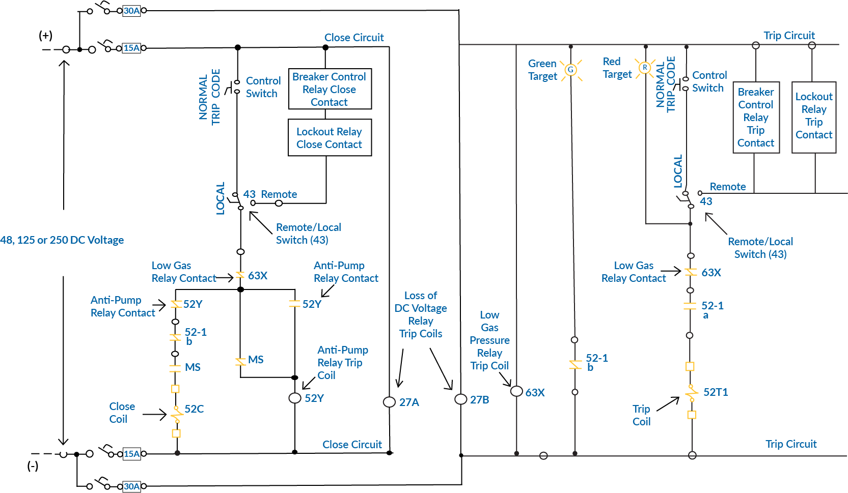
- DC MCBs are installed in the positive and negative DC supply lines.
- They protect the entire control circuit, including:
- Close circuit components (close coil, control switch, relay contacts)
- Trip circuit components (trip coil, lockout relay contacts)
- Anti-pump relay circuit
- Auxiliary contacts and indicating circuits (green/red target lamps)
- Local / remote control switching circuits
- This configuration ensures:
- Complete isolation of control circuits during maintenance
- Protection against short circuits in control wiring
- Independent protection of close and trip functions
- Safe operation of all auxiliary functions
- Protection of supervision circuits
- The DC MCB rating is selected based on:
- Control voltage level (48V, 125V, or 250V DC)
- Close and trip coil current requirements
- Number of auxiliary devices in the circuit
- Coordination with upstream protection
Additionally, in ungrounded DC systems, the voltage potential can exceed the nominal system voltage, making higher-rated DC MCBs safer and more suitable for these applications.
Dual Auxiliary DC Control Power System
In a typical dual auxiliary DC control power system, DC MCBs are used in the auxiliary DC panels as distribution circuit breakers (DCA1-DCA4 in Panel A and DCB1-DCB4 in Panel B). These DC MCBs protect individual control circuit branches, while the DC-Main and DC-Tie breakers are typically larger frame circuit breakers for main power distribution.
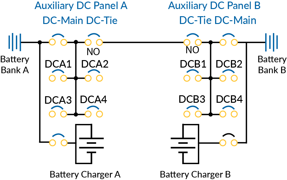
- The system operates as follows:
- Each battery bank feeds its respective auxiliary DC panel through a DC-Main breaker
- The auxiliary DC panels contain multiple DC MCBs (DCA1-DCA4 and DCB1-DCB4) for branch circuit protection
- DC-Tie breakers between panels provide redundancy
- Each battery bank has its dedicated charger with protective devices
- This configuration ensures:
- Selective coordination between main and branch circuit protection
- Independent operation of critical control circuits
- Redundant power sources for enhanced reliability
- Protection for individual control circuit branches
Remote Monitoring and SCADA Systems
In modern switchgear installations, remote monitoring and control are critical for efficient power management. Many essential devices in these systems operate on DC power (typically 12V to 48V DC), supplied by battery-backed systems for reliability. DC MCBs protect the branch circuits that supply power to these devices, ensuring safe and uninterrupted operation.
These protected branch circuits supply power to:
- Remote Terminal Units (RTUs): Enable data acquisition and remote control.
- Communication Gateways: Facilitate seamless data exchange between control systems.
- Protocol Converters: Enable interoperability between different communication standards.
- Digital Input/Output Modules: Provide control and status feedback for automation.
- Ethernet Switches & Fiber Optic Converters: Ensure reliable network communication in substations and industrial settings.
DC MCBs rated for 250V DC per pole offer superior protection by preventing overcurrent faults while maintaining coordination with upstream battery protection systems. Their ability to handle DC arc interruption enhances reliability, reducing the risk of downtime in remote monitoring and SCADA applications.
Interlocking Circuit Protection
Interlocking systems prevent unsafe switching operations in switchgear. Their protection is critical because:
- Multiple breakers and disconnectors are interconnected
- Operations must occur in specific sequences
- Mechanical and electrical interlocks work together
- Safety of personnel and equipment depends on reliable operation
DC MCBs in interlocking applications provide:
- Independent protection for each interlocking zone
- Clear isolation points for maintenance
- Status monitoring capability
- Coordination with main circuit protection
- Protection against wiring faults
Conclusion
The future of switchgear control circuit protection lies in simplified, reliable solutions that reduce complexity while enhancing protection. 250V DC per pole MCBs deliver exactly that, making them the clear choice for modern switchgear installations.
Explore our wide range of high-performance DC MCBs at c3controls.com today! For detailed specifications and ordering information, please contact our technical support team.
----------------------------------------
Disclaimer:
The content provided is intended solely for general information purposes and is provided with the understanding that the authors and publishers are not herein engaged in rendering engineering or other professional advice or services. The practice of engineering is driven by site-specific circumstances unique to each project. Consequently, any use of this information should be done only in consultation with a qualified and licensed professional who can take into account all relevant factors and desired outcomes. The information was posted with reasonable care and attention. However, it is possible that some information is incomplete, incorrect, or inapplicable to particular circumstances or conditions. We do not accept liability for direct or indirect losses resulting from using, relying or acting upon information in this article.
OUR PRODUCTS
COMPANY / SERVICES
c3controls Headquarters, USA
664 State Street
Beaver, PA 15009
TEL 724.775.7926
FAX 724.775.5283