Introduction
When you first think of an electrical panel, it is likely that you would think of common power and control products such as circuit breakers, terminal blocks, relays, contactors and more. However, you likely wouldn’t consider the component that provides the structure and mechanical support needed for all the electrical products in a panel to function properly — DIN rail. Before discussing this first panel essential, here’s a first look for you.
Description and Benefits
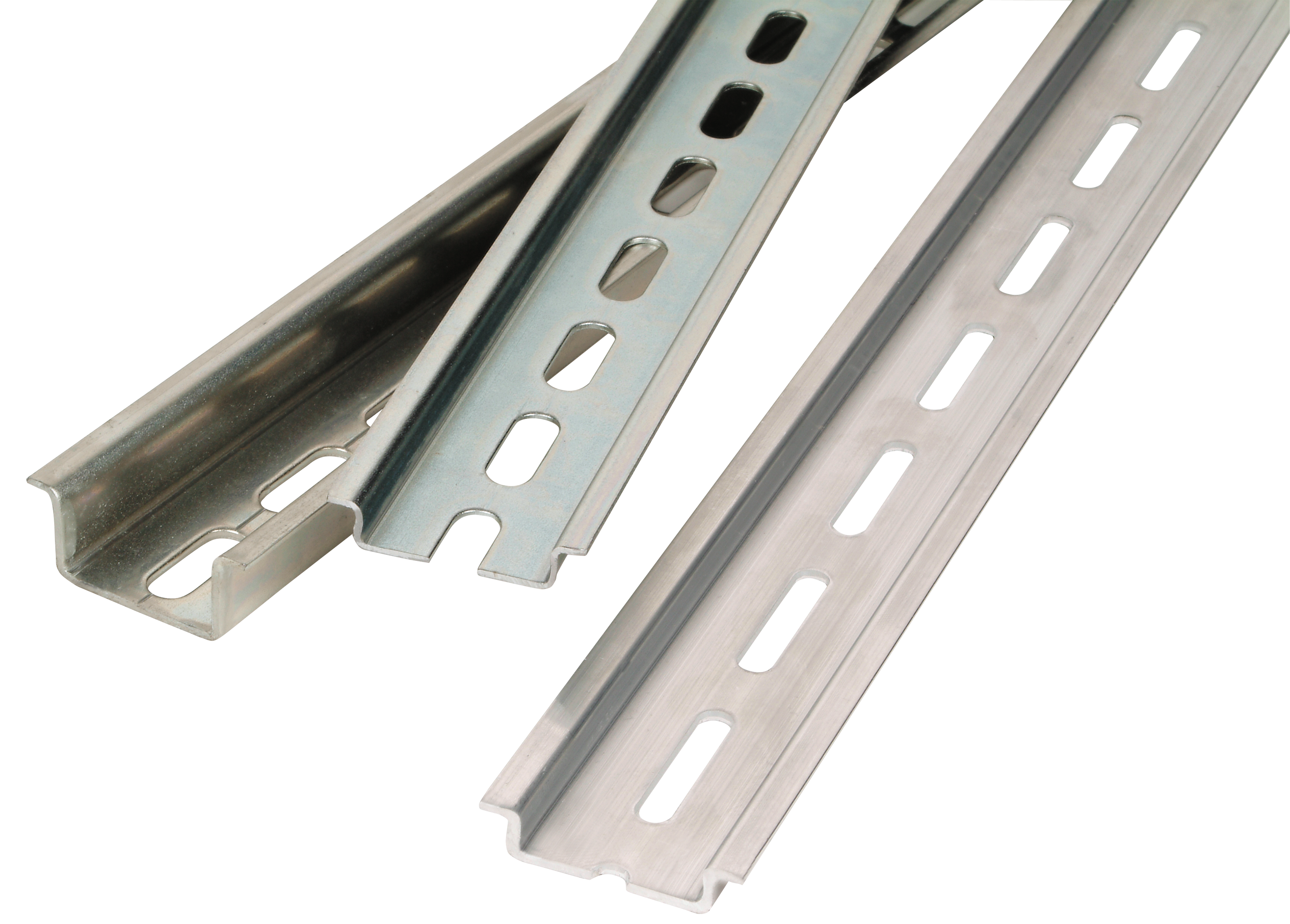
DIN rail is a metallic rail that can be fastened to a surface to mount industrial control equipment. Most commonly, DIN rail is manufactured from copper, aluminum or steel with a zinc-plated/chromate finish. Zinc-plated steel is a popular all-around solution considering its cost-effectiveness, strength and resistance to shock and corrosion. Despite having a metallic property, the primary function of DIN rail is to provide support rather than to conduct an electrical current, as a busbar would. Standard DIN rail is 35mm wide, slotted and supplied in both 1 and 2 meter lengths. However, many enclosures will feature cut-to-size DIN rail to meet specific panel requirements.
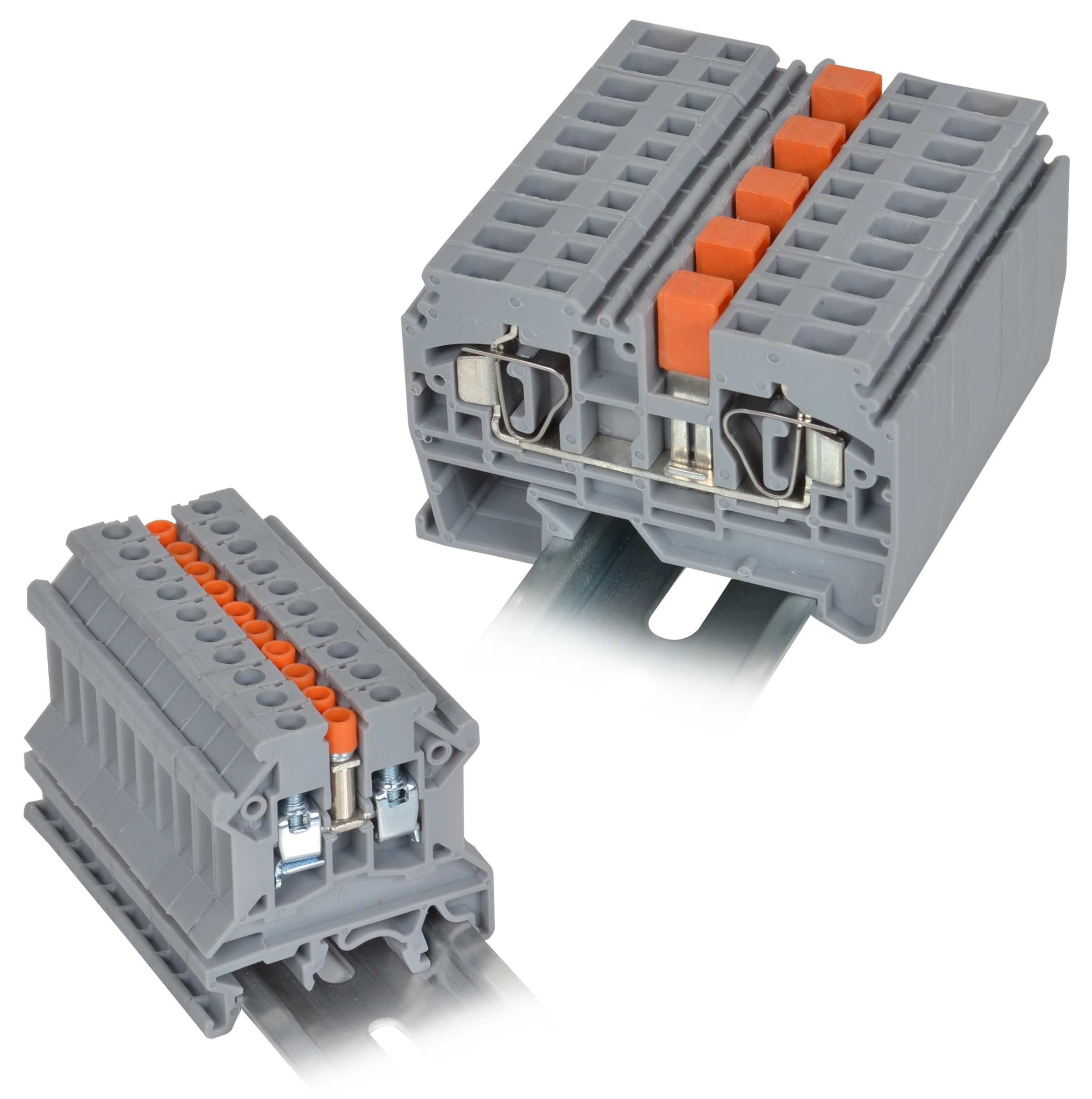
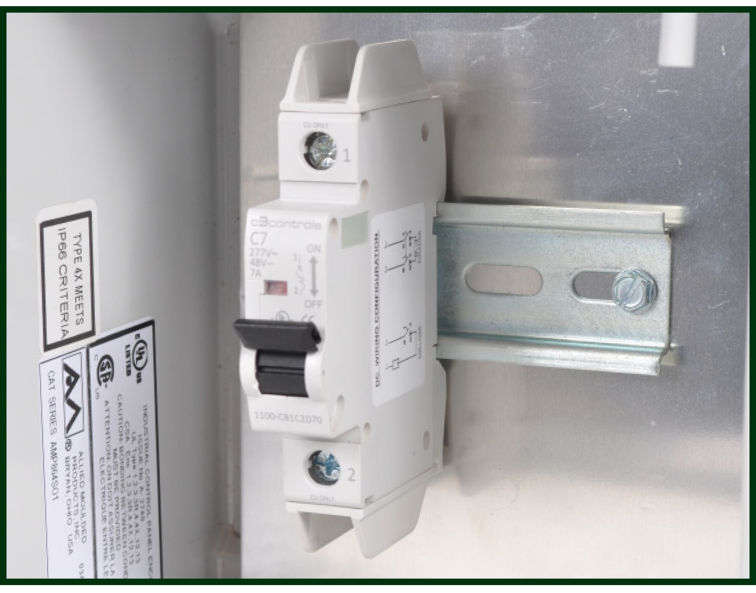
Utilizing DIN rail is far more effective and efficient than mounting individual products directly on the panel. Not only does DIN rail optimize limited space, it provides a standard for the components it supports — almost all circuit breakers, terminal blocks and other key electrical products are designed to comply with standard DIN rail specifications.
History
While DIN rail is ubiquitous with control panels today, this wasn’t the case almost a century ago. In the late 1920s, German company RWE, Rheinisch-Westfälisches Elektrizitätswerk, encountered a problem that required a way to mount electrical products closer together on a panel board. Working with another German manufacturer, the Phoenix Electrical Supply Company (now Phoenix Contact), the concept for DIN rail surfaced in 1928 with the G-rail (later, we will discuss types of DIN rail).
The term “DIN” comes from the German national organization for standardization, Deutsches Institut für Normung, responsible for defining the original industrial specifications for rail assembly. Originally constructed as a porcelain tray housing a busbar, the DIN rail concept was refined in the 1950s to reflect the current metal design we see today. Compatible standards were then adopted by organizations such as the International Electrotechnical Commission (IEC) and the National Electrical Manufacturers Association (NEMA) in the United States. As one of the few products that is widely accepted as a global standard, DIN rail is now incorporated in almost every panel and electrical project across the world.
Types
Electrical components and panels are manufactured to fit one of several DIN rail types such as:
- Miniature Top-Hat Rails: At 15mm wide and 5.5mm deep, miniature top-hat rails are the smallest size of DIN rail. Also known as TS15 rails, these symmetrical rails are best suited for smaller components or applications in which limiting space is critical.
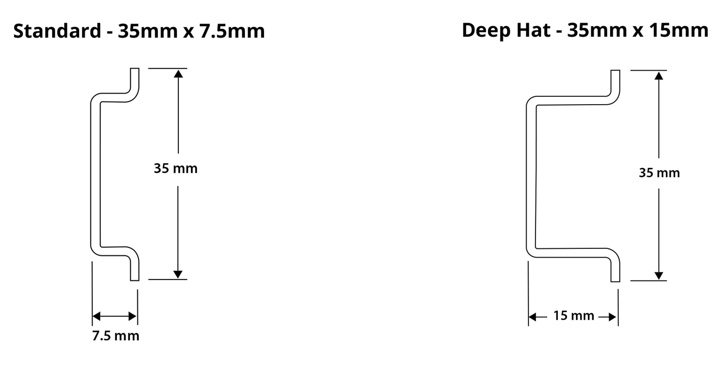
- Top-Hat Rails: Top-hat rails look exactly like their miniature version except they are 35mm wide and 7.5mm deep. Also known as TS35 rails, there is also a 35mm x 15mm ‘deep hat’ version for added strength and durability.
- G32 Rails: As their name suggests, these rails are shaped like the letter ‘G’ and are 32mm wide. Also known as TS32 or ‘G-rails’, their asymmetrical design helps prevent incorrect installation while offering additional support for larger and/or heavier products.
- C32 Rails: As their name suggests, these symmetrical rails are shaped like the letter ‘C’ and are 32mm wide. With a shape opposite to that of top-hat rails, these rails are less common in modern applications and often require an adapter for installation.
The variation of DIN rail required depends on the application to which it is being applied. Top-hat rail is often regarded as the industry standard and is designated IEC/EN 60715. The common configurations of top-hat rail, at both 1 and 2 meter lengths, can be seen below:
Best Practices
If you are applying DIN rail to a panel yourself, here are a few best practices to consider:
- Make sure your DIN rail is compatible with your panel! If your enclosure is metal rather than polycarbonate (which can safely pair with any DIN rail), you will need a rail constructed of the same metal as the enclosure.
- Confirm that your DIN rail meets common standards and is the right size for your products. While Top-Hat, 35mm DIN rail is standard, some products may require 15mm or 32mm mounting.
- Determine which mounting accessories are required — consider end plates, separator plates, end barriers and support brackets.
- Outline how you will mount components prior to installation. Consider the following:
- Similar components should be mounted together to limit end/separator plates.
- AC products should be kept separate from DC products.
- Products should be arranged so that wires don’t pass over other components.
c3controls DIN Rail Offering
c3controls offers two types of 35mm symmetrical DIN rail; steel and aluminum. Our steel DIN rail is zinc with clear chromate plating and is available standard or ‘deep hat’ in both 1m (3.28 ft.) and 2m (6.56 ft.) lengths. Our standard aluminum version is available in a 1m length. All rails are slotted and simply fasten by screws to the mounting surface — no special bracket or hardware is needed. Circuit breakers, terminal blocks and other electrical products easily snap on to the rail for fast and easy installation and removal.
c3controls also offers a variety of mounting accessories such as end plates, separator plates, end barriers and support brackets.
Check out our DIN rail offerings!
Panel Solutions
For your complete panel needs, c3controls operates a UL508A certified panel shop serving the OEM and panel builders across a wide variety of industries. Check out our enclosed panel solutions!
c3controls Panel Essentials Papers:
- Series 1: DIN Rail
- Series 2: Wire Duct and Terminal Blocks (for wire and cable management)
- Series 3: UL508A Control Panel Design Considerations
- Series 4: Electrical Control Components
- Series 5: Control Panel Industry Trends
----------------------------------------
Disclaimer:
The content provided is intended solely for general information purposes and is provided with the understanding that the authors and publishers are not herein engaged in rendering engineering or other professional advice or services. The practice of engineering is driven by site-specific circumstances unique to each project. Consequently, any use of this information should be done only in consultation with a qualified and licensed professional who can take into account all relevant factors and desired outcomes. The information was posted with reasonable care and attention. However, it is possible that some information is incomplete, incorrect, or inapplicable to particular circumstances or conditions. We do not accept liability for direct or indirect losses resulting from using, relying or acting upon information in this article.
ISO 9001:2015
Certified
17+ Million Product
Configurations
Lifetime
Warranty
Guaranteed
Same-Day Shipping
Advantage Pricing
Save Up To 40%
c3controls Headquarters, USA
664 State Avenue
Beaver, PA 15009